KYN28-12 TYPEIARMORED MOVABLE AC METALENCLOSED SWITCHGEAR
OVERVIEW
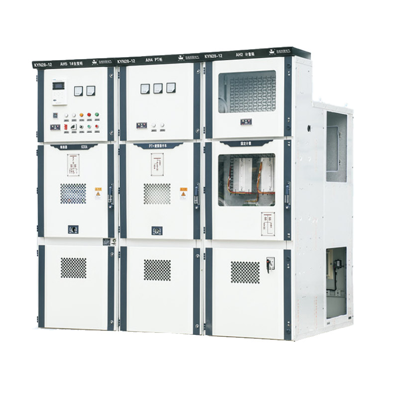
KYN28-12 armored movable AC metal enclosed switchgear is suitable for 3.6-12kv three-phase Ac 50Hz power grid, as it receives and distnibuteselectrical energy, and controls, monitors, and protects circuits. Can be used for single bus, single bus segmented systems, or dual bus systems. Theswitchgear complies with the requirements of lEc298 "AC Metal Enclosed Switchgear and Control Equipment for Rated Voltages above 1ky and below52k", 1EC694 "Common Terms for High Votage Switchgear and Control Equipment, Cchinas"GB3906 3-35kV AC Metal Enclosed Switchgear" and DlA04lndoor Ac High Voltage Switching Cabinet Ordering Conditions, Germany's DINVDE0670 'Ac Switchgear for Rated Voltages above 1kv" and otherstandards, And it has complete and reliable anti misoperation functions
MODEL AND MEANING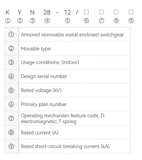
MAIN FEATURES
KYN28-12 armored movable AC metal enclosed switchgear (hereinafter refered to as switchgear) is a new type of product designed and developedoy our company on the basis of absorbing advanced domestic manufacturing technology. i can replace various old metal enclosed switchgear, such asKYN1-12, JYN2-12 and other series of products, its products have the following obvious advantages.1. The outer shell of the product is completely assembled with bots, with high mechanical strength,efectively ensuring the neatness and aesthetics of theproduct. The cabinet door is coated with soray plastic, which has strong imoact resistance and coosion resistance. The product casing has a protectiorlevel of lP4X. (Can be changed to iron plate according to customer needs)2.The switch of this product can be equipped with ABB's VD4 vacuum circuit breaker, C3 series fixed load switch, and various domestic series vacuumcircuit breakers (such as VS1, VH1, VK, ZN28) to replace similar foreign products.3.Regardless of the type of circuit breaker selected, the air insulation distance ofthe bare conductor can be guaranteed to be greater than 125mm, andthe composite insulation distance can be greater than 60mm. ts circuit breakers all have the unique advantages of long service life, less maintenance and small size
NORMAL CONDITION
Environmental temperature: upper limit+40 `C , lower limit -10 °C
Relative humidity: daily average not exceeding 95%, monthly average not exceeding 90%
Altitude: not exceeding 1000m;
Shock resistance: not exceeding 8 degrees;
In situations where there is no risk of fire, explosion, severe pollution, chemical corrosion, or severe vibration,Note: When ordering this product beyond the above conditions, please consult with our company
COMPLIANT WITH STANDARDS
GB 3906 3-35KVAC Metal Enclosed Switchgear
GB/T1 1022 Common Technical Requirements for High Voltage Switchgear and Control Equipment Standards
DL/T404 Technical Conditions for Ordering indoor AC High Voltage Switches
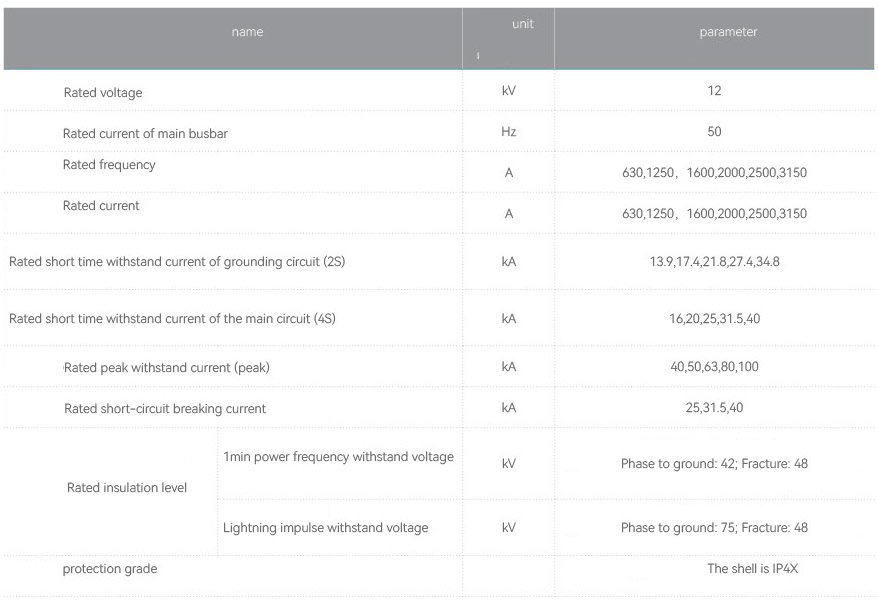
MAIN TECHNICAL PARAMETERS
STRUCTURAL CHARACTERISTICS OF SWITCHGEAR
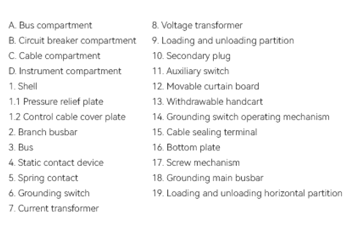
The switchgear is designed according to the amored metal enclosed switchgear in GB3906-91. Figure 1: The switchgear consists of two main parts; aixed cabinet body and a withdrawable component (refered to as a handcart). The shell of the cabinet body and the partitions of each functional unitare connected by bolts. The protection level of the switchgear shel is lP4X, and the protection level when the circuit breaker room door is opened is 1P2xThe switchgear can be equipped with a vacuum circuit breaker handcart or a fixed load switch. Equipped with overhead incoming (outgoing) lines, cablebutaoing ines, and other functional soluions, The switchgear can be instaled in a double cabinet arrangement that is. in a back to back or face to facdouble row arrangement
INSTALLATION OF SWITCHGEAR
1. According to the engineering needs and drwings, transpot the switchgear to a specific location.lf a long row of switchgear is arranged (such as morethan 10 units), the cabinet assembly work should start from the middle part;2. lt is strictly prohibited to use specific transportation tools such as cranes or forklifts to pry with rollers;3, Extract the circuit breaker handcart from the switchgear and store it in a safe place,4. Loosen the fixing bolts in front of the busbar compartment and remove the vertical partition 9;5. Loosen the fixing bolts of the horizontal partition 19 below the circuit breaker compartment and remove the horizontal partition,6. Loosen and remove the base plate 1ó;
7.Remove cover plates 1 and 2 from the control wire slot on the left side of the switchgear, Remove the right front control slot cover simultaneously,3. install switch cabinets one by one on the basis, including both horizontal and vertical aspects. The unevenness of switch cabinet installation shall not
exceed 2mm;
9. After the switchgear is fully assembled (spliced), it can be connected to the foundation channel steel with foundation screws or welded firmly with thefoundation channel steel with electric welding.
ORDERING INSTRUCTIONS
The following technical information should be provided when ordering.1. Main circuit scheme diagram number, purpose, main line system diagram,distribution room layout plan and arrangement configuration diagram, etc;2. Reauirements for contro, measurement, and protection functions of switchgear, as wel as requirements for other locking and automatic devices,3. The model, specification, and quantity of the main electrical components inside the switchgear,4. f a busbar bridge connection is required between switchgear or incoming cabinets, specific requirements such as the rated curent carying capacity oithe busbar bridge, the span of the busbar bridge, and the height from the qround should be provided.5. When switchaear is used in special environmental conditions, detailed instructions should be provided when ordering,6.Neaotiate with the manufacturer to resolve special reauirements
OUTLINE DIMENSIONS OF SWITCHGEAR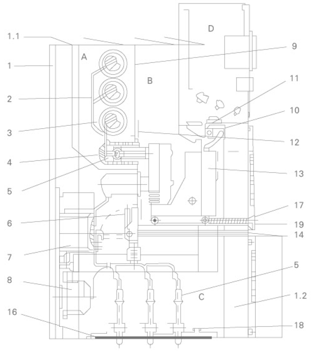
Contact with us